Last updated on: August 18, 2025
Bar Bending Schedule Basics and Formulas | BBS Steel Calculation
Bar bending schedule basic formulas play an essential role in the construction industry, as they are used to calculate the required steel quantity for a given concrete design.
The process of preparing bar bending schedules is crucial in determining the amount of reinforcement required and the detailing of working drawings.
This procedure requires a certain level of expertise and calculation, which can be efficiently carried out using computer programs or software’s.
The main purpose of such programs is to determine the bend length, cutting length, hook length, weight of bar and other essential aspects for the quantity of reinforcement calculation.
This article will provide an overview of the basics of bar bending schedule formulas, highlighting their significance and benefits for steel calculations for RCC members in construction. Before reading this article you first read about the followings:
What is Bar Bending Schedule (BBS)?
A Bar Bending Schedule (BBS) is a document that provides a detailed list of all the reinforcing steel bars required for a particular structure. It includes the diameter of each bar, the length of each bar, the number of bars required, shape, size and the weight of each bar.
“Bar bending schedule is not just a document, it’s a critical tool for ensuring the strength and stability of a structure. It represents the careful planning and attention to detail that goes into every construction project.”
Basics of Bar Bending Schedule (BBS) Formulas:
Before starting the preparation of the bar bending schedule, we should know about the basics of bar bending schedule formulas that we will use during the steel calculation of BBS:
Important Points to Understand Before Creating a Rebar Schedule:
- Location of Bar: The placement and orientation of the reinforcement bars within the structural element.
- Type of Bar: The specific type of reinforcement bar used in the construction project.
- Size of Bar: The diameter of the reinforcement bar.
- Cutting Length of Bar: The length of the reinforcement bar required for a specific structural element.
- Number of Bars: The total number of reinforcement bars needed for a particular structural element.
- Bending Detail of Bars: The specific angles and shapes required for bending the reinforcement bars to match the structural design.
- Total Quantity of Steel: The overall amount of reinforcement steel required for the entire project.
Diameter and Unit Weight of Bars in Kg/ft (Imperial):
| Dia in No.s | Dia in Inches | Unit Weight (Kg/ft) |
| #3 | 3/8″ | 0.170 |
| #4 | 1/2″ | 0.302 |
| #5 | 5/8″ | 0.473 |
| #6 | 3/4″ | 0.680 |
| #7 | 7/8″ | 0.926 |
| #8 | 1″ | 1.21 |
| #9 | 9/8″ | 1.53 |
| #10 | 10/8″ | 1.89 |
Standard Length of Reinforcement Bar in Feet (ft):
The standard length of a reinforcement bar, also known as a rebar, is typically 40 feet long. However, the length of the rebar can vary depending on the manufacturer and the specific project requirements.
It’s important to note that the length of the rebar can be cut to fit the specific dimensions of the structural elements as needed.
Diameter and Unit Weight of Bars in Kg/m (Metric):
| Dia in mm | Unit Weight (Kg/m) |
| 6 mm | 0.222 |
| 8 mm | 0.394 |
| 10 mm | 0.616 |
| 12 mm | 0.888 |
| 16 mm | 1.57 |
| 20 mm | 2.46 |
| 25 mm | 3.85 |
| 28 mm | 4.83 |
| 32 mm | 6.31 |
| 36 mm | 7.99 |
| 40 mm | 9.86 |
Standard Length of Reinforcement Bar in Meter (m):
The standard length of a reinforcement bar in meter is 12 meters long.
Standard Length of Reinforcement Bar in Different Countries:
| Country | Standard Length in Feet | Standard Length in Meter |
| United States | 20 feet | 6.096 meters |
| United Kingdom | 40 feet | 12 meters |
| Pakistan | 40 feet | 12 meters |
| India | 40 feet | 12 meters |
| Australia | 40 feet | 12 meters |
| Canada | 50 feet | 15 meters |
| Philippines | 20 feet | 6 meters |
Unit Weight of Steel Bars per Foot Formula (in Kg/ft)
CASE – 1:
Unit Weight of Steel Bar Per Feet = W = D2 / 533
where ‘D’ is in mm
For Example:
Diameter of Bar = D = 10 mm
Unit Weight of Steel Bar Per Feet = W = D2 / 533 = (10 x 10) / 533 = 0.188 Kg/ft
CASE – 2:
Unit Weight of Steel Bar Per Feet = W = D2 / 52.896
where ‘D’ is in # (Numbers)
For Example:
Diameter of Bar = D = #4
Unit Weight of Steel Bar Per Feet = W = D2 / 52.896 = (4 x 4) / 52.896 = 0.302 Kg/ft
Unit Weight of Steel Bars per Meter Formula (in Kg/m)
Unit Weight of Steel Bar Per Feet = W = D2 / 162
where ‘D’ is in mm
For Example: Dia of Bar = D = 8 mm
Unit Weight of Steel Bar Per Feet = W = D2 / 162 = (8 x 8) / 162 = 0.39 Kg/m
How to Calculate the Weight of Steel Bar with Required Length:
Weight of Steel Bar in Kg/ft3:
Total Weight of Steel Bar = W = D2 / 533 x Length of Bar
Where D is in mm , Length of Bar in feet
For Example; Dia of Bar = 10 mm and Length of Bar = 40 feet
so, The Total Weight of Steel Bar = W = D2 / 533 x Length of Bar = (10 x 10)/533 x 40 = 7.50 Kg/ft3
Weight of Steel Bar in Kg/m3:
Total Weight of Steel Bar = W = D2 / 162 x Length of Bar
Where D is in mm , Length of Bar in m
For Example; Dia of Bar = 8 mm and Length of Bar = 12 m
so, The Total Weight of Steel Bar = W = D2 / 162 x Length of Bar = (8 x 8)/162 x 12 = 4.74 Kg/m3
Bend Deduction formula for Reinforcement:
When we bend a steel bar, the length of bar slightly increased due to scratching in the bending area. So cutting length is taken lesser than required length. It is usually taken:
- For 45 Degree Bend = 1d
- For 90 Degree Bend = 2d
- For 135 Degree Bend = 3d
- For 180 Degree Bend = 4d

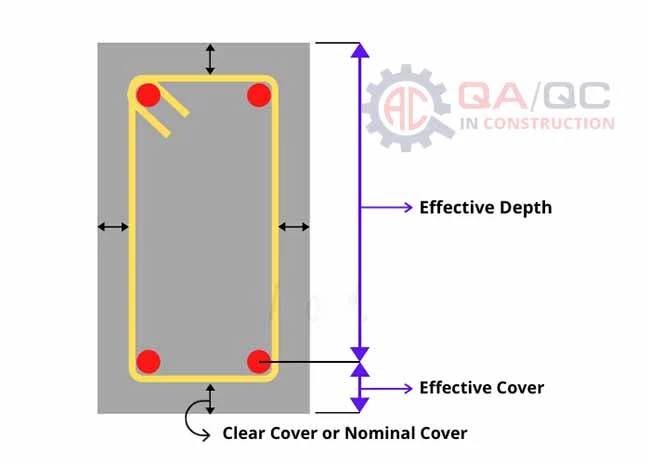
Types of Concrete Covers in Reinforced Concrete:
In reinforced concrete, the concrete cover is the shortest distance between the surface of embedded reinforcement and the outer surface of the concrete. Types of concrete covers are:
- Minimum Cover: This is the minimum thickness of concrete cover required to protect the reinforcing steel from corrosion and to ensure adequate bonding. The minimum cover depends on the type of exposure (i.e., whether the structure will be exposed to water, soil, or air) and the size of the reinforcing steel.
- Nominal Cover: This is the cover specified in the design of the reinforced concrete structure, which is typically greater than the minimum cover to provide additional protection to the reinforcing steel.
- Effective Cover: This is the actual thickness of concrete cover provided in the construction of the reinforced concrete structure, which may be greater or less than the nominal cover due to variations in construction practices.
Effective Cover = Clear cover + Total Diameter of Stirrup (d) + (Diameter of main reinforcement bar (D))/2
- Clear Cover: This is the distance from outer surface of concrete to the nearest surface of the reinforcing bar. Clear cover is important for ensuring proper placement of reinforcing steel and preventing congestion.
Clear Cover = Effective Cover – Dia of Reinforcing Bar
| Clear Cover for Different Concrete Structures | ||
| Member | In Imperial | In Metric |
| Footing | 2 in | 50 mm |
| Column | 1.5 in | 40 mm |
| Beam | 1 in | 25 mm |
| Slab | 0.8 in | 20 mm |
| Staircase | 0.6 to 0.8 in | 15 to 20 mm |
Overlapping formula for Steel Reinforcement:
During placing the steel in RC structures if the required length of a bar is not sufficiently available to make a design length then lapping is done. Lapping means overlapping of two bars side by side to achieve required design length.

Column Neck to Column Overlap = L = 40d to 50d
Column to Column or Beam Overlapping = L = 50d
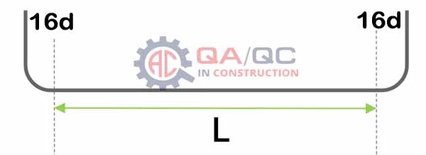
Development Length for Dowel Bars = L = 16d
Generally Overlapping when 12m (40ft) bar finish = L = 50d
Spacing in Reinforcement:
Distance between two reinforcement bars
Minimum Spacing between Two Bars = Maximum Size of Aggregate + 5mm
Number of Bars Formula:
No. of Bars = (Span/Spacing) + 1
Number of Bars along Lx = (Ly / Spacing) + 1
Number of Bars along Ly = (Lx / Spacing) + 1
Number of Stirrups Formula:
No. of Stirrups = (Actual Length of Column or Beam / Spacing) + 1
Cutting Length of Bar Formulas:
Cutting length of reinforcement is the length of the reinforcement bar required to be embedded or overlapped with another bar in a concrete structure, calculated based on the development length required for the bar.
Let’s we find different types of cutting lengths by using bar bending schedule formulas:
Cutting Length of Main Bar with Hook Formula (180 Deg):

Length of Hook = 8d + 4d = 12d where ‘d’ is diameter of bar
Bend Deduction for 180 Degree = 4d
Cutting Length of Main Bar formula = L = Span – (2 x CC) + (2 x Length of Hook) – (2 x Bend Deduction)
Cutting Length of Main Bar = L = Span – (2 x CC) + (2 x 12d) – (2 x 4d)
For Example:
Overall Span = 6 m,
Concrete Cover CC for Slab = 20 mm = 20/1000 = 0.020,
Dia of Bar = 12 mm = 0.012 m so,
Cutting Length of Main Bar = L = 6 – (2 x 0.020) + (2 x 12 x 0.012) – (2 x 4 x 0.012) = 6.152 m
Cutting Length of Main Bar with Bend Formula (90 Degree):
Length of Hook = 12d + 4d = 16d
where ‘d’ is diameter of bar Bend Deduction for 90 Degree = 2d
Cutting Length of Main Bar formula = L = Span – (2 x CC) + (2 x Length of Hook) – (2 x Bend Deduction)
Cutting Length of Main Bar = L = Span – (2 x CC) + (2 x 16d) – (2 x 2d)
For Example:
Overall Span = 7 m, Concrete Cover CC for Slab = 20 mm = 20/1000 = 0.020, Dia of Bar = 12 mm = 0.012 m
so, Cutting Length of Main Bar = L = 7 – (2 x 0.020) + (2 x 16 x 0.012) – (2 x 2 x 0.012) = 7.296 m
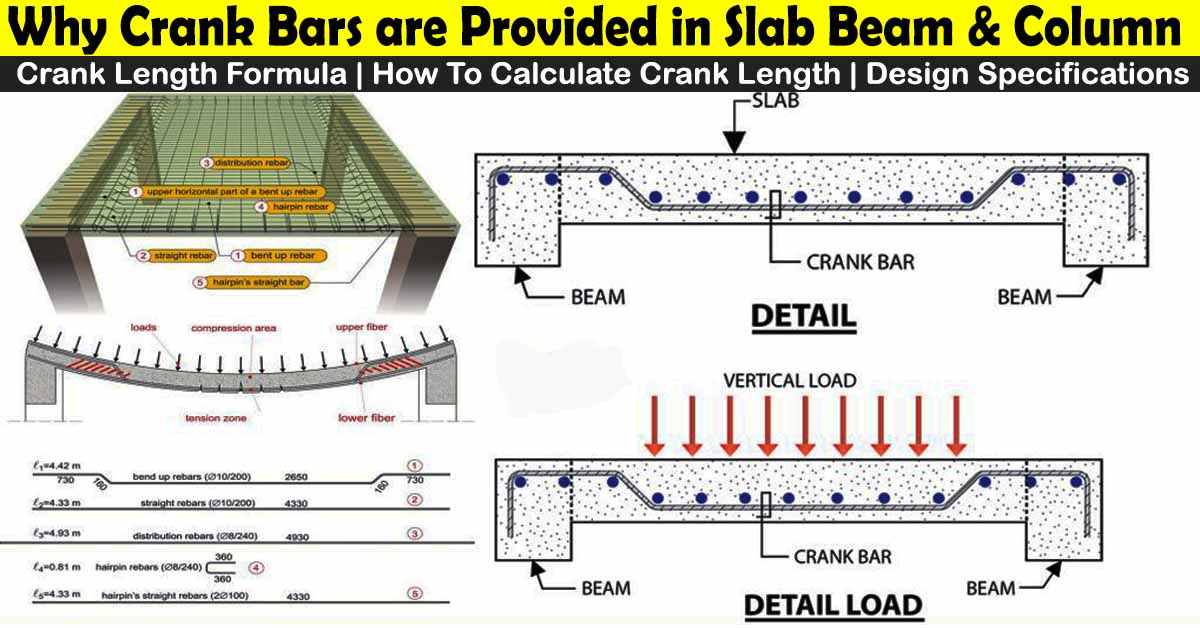
Cutting Length of Crank or Bent Up Bar Formula:
A Bent up bar is also called as crank bar and It is provided to make RCC Slab safe from compressive stresses.

Length of Hook = 8d + 4d = 12d
where ‘d’ is diameter of bar
Bend Deduction for 180 Degree = 4d
Bend Deduction for 45 Degree = 1d
Crank Length formula for Different Angles:
- Crank Length for 30 Degree = 0.27h
- Crank Length for 60 Degree = 0.58h
- Crank Length for 45 Degree = 0.42h (We use this now)
where h = Slab thickness – (2 x CC) – (2 x half Dia of Bentup Bar)
Cutting Length of Bentup Bar formula = L = Clear Span + (2 x Breadth of Beam) – (2 x CC) + (2 x Crank Length) – (4 x 45 Deg Bend Deduction) – (2 x Length of Hook) – (2 x 180 Deg Bend Deduction)
Cutting Length of Bentup Bar = L = Clear Span + (2 x Breadth of Beam) – (2 x CC) + (2 x 0.42 x h) – (4 x 1 x d) – (2 x 12 x d) – (2 x 4 x d)
For Example:
Clear Span = 1800 = 1.8 m, Breadth of Beam = 300 mm = 0.300 m,
Concrete Cover CC for Slab = 20 mm = 20/1000 = 0.020 m,
Dia of Bentup Bar = 12 mm = 0.012 m,
Slab thickness = 150 mm = 0.150 m
First we find the value of h = 0.150 – (2 x 0.020) – (2 x 0.006) = 0.098 m
Cutting Length of Bentup Bar = L = 1.8 + (2 x 0.300) – (2 x 0.020) + (2 x 0.42 x 0.098) – (4 x 1 x 0.020) – (2 x 12 x 0.020) – (2 x 4 x 0.020) = 1.722 m
Cutting Length of Extra Bars Formula:
Length of Extra Bars = L/4 to L//5
Cutting Length of Rectangular Stirrup Formula:

Cutting Length of Rectangular Stirrup = L = (a x 2) + (b x 2) + Hook Length – Bend Deduction
Where a = A – (2 x Concrete Cover) and b = B – (2 x Concrete Cover)
Hook Length = 2 x 12d (for 135 Degree Bend, in case of 90 degree bend should be 10d) Bend Deduction 90 = 3 x 2d Bend Deduction 135 = 2 x 3d
Cutting Length of Rectangular Stirrup = L = (a x 2) + (b x 2) + (2 x 12 x d) – (3 x 2 x d) – (2 x 3 x d)
Cutting Length of Triangular Stirrup Formula:

Cutting Length of Triangular Stirrups = L = (H x 2) + a + Hook Length – Bend Deduction
Where H = √X2 + Y2 therefore X = a / 2 and Y = b / 2
a = A – (2 x Clear Cover) b = B – (2 x Clear Cover)
- Hook Length = 2 x 10d
- Bend Deduction for 135o = 2 x 3d
- Bend Deduction for 120o = 2 x 1.33d (Because the outer bend is 60o)
Cutting Length of Triangular Stirrup = L = (H x 2) + a + (2 x 10 x d) – (2 x 3 x d) – (2 x 1.33 x d)
Cutting Length of Diamond Stirrup Formula:

Cutting Length of Triangular Stirrups = L = (H x 4) + Hook Length – Bend Deduction
Where,
- H = √X2 + Y2
- therefore X = a / 2
- and Y = b a = A – (2 x Clear Cover),
- Hook Length = 2 x 10d
- Bend Deduction for 90o = 3 x 2d
- Bend Deduction for 135o = 2 x 3d
Cutting Length of Diamond Stirrup = L = (H x 4) + (2 x 10 x d) – (3 x 2 x d) – (2 x 3 x d)
Cutting Length of Circular Stirrup Formula:

Cutting Length of Circular Stirrup = L = (Pi x d) + Hook Length – Bend Deduction
Where,
- d = D – (2 x Clear Cover) – Dia of Bar
- Hook Length = 2 x 10d
- Bend Deduction for 135o = 2 x 3d
Cutting Length of Circular Stirrup = L = (Pi x d) + (2 x 10 x d) – (2 x 3 x d)
Cutting Length of Chair Bar Formula:
Chairs are used in reinforcement because: they hold the reinforcement in position and maintain the distance between top reinforcement and bottom reinforcement, so to find the cutting length of chair bar formula is;
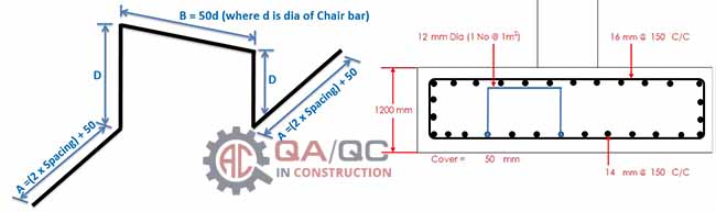
Cutting Length of Chair Bar Formula = L = 2A + 2D + B – Bend Deduction
Where,
- A = (2 x Spacing) + 75 mm
- B = 50d
- D = Footing Height – [(Upper + Lower Concrete Cover) + (Upper MB Dia + Upper DB Dia) + Lower MB Dia
- Bend Deduction for 90o = 4 x 2d
Cutting Length of Chair Bar Formula = L = 2A + 2D + B – (4 x 2 x d)
Development Length of Bar Formula:
Development Length can b characterized as the length of the bar required for transferring the stress into the concrete, so the development length formula is;
Development Length of Bar = Ld = (db x fs) / (4 x τbd) Where,
- db is the nominal dia of the bar,
- fs is the stress in the bar (reinforcement) at the section considered at design load (for fully stressed bar, fs = 0.87 fy)
- τbd is the design bond stress as per Table below.
| Grade of concrete | M20 | M25 | M30 | M35 | M40 and above |
|---|---|---|---|---|---|
| Design bond stress , MPa | 1.2 | 1.4 | 1.5 | 1.6 | 1.9 |
| For fully deformed bars | 1.18 | 1.37 | 1.54 | 1.71 | 1.87 |
Standard Hook and Bend Length Formula as Per ACI 318:

Steps Used in Preparation of Bar Bending Schedule or BBS Calculations:
The following steps are used to prepare Bar Bending Schedule or BBS Calculations:
- Calculate the Length of Bar
- Number of Bars = Opposite Length / Spacing + 1 , Number of Stirrups = Actual Length / Spacing + 1
- Total Length of Bar = Length of Bar x Number of Bars
- Check the Diameter of Bar
- Weight Per meter = D2 / 162 Kg/m or Weight Per feet = D2 / 533 Kg/ft
- Total Weight of Steel = Total Length of Bar x D2 / 162 Kg/m3 or Total Length of Bar x D2 / 533 Kg/ft3
Conclusion for Bar Bending Schedule Formulas:
In conclusion, bar bending schedule formulas are instrumental in the calculation and determination of the necessary steel bars in a construction project.
These formulas serve as a guide for civil engineers and construction professionals to easily determine the weight and dimensions of steel required for a specific structure.
The formulas can be presented in a sheet format, usually in PDF or Excel, which can be downloaded and easily referenced during construction.
The use of bar bending schedule formulas has revolutionized the steel construction industry, making it easier and more efficient.
Therefore, it is imperative for professionals in the field of Civil Engineering to fully understand the concept of bar bending schedules and their formulas.
Bar Bending Formula Video Tutorial:
Lets understand the basic concepts before preparation of bar bending schedule in excel by using Bar Bending Schedule formulas and calculation.
This video tutorial will explain the all BBS formulas with comprehensive detail must watch:
Bar Bending Schedule Formulas PDF Download
Please follow the link for Bar Bending Schedule Formulas PDF Download
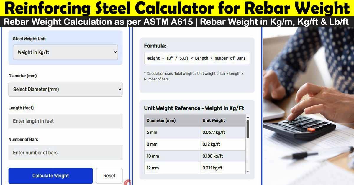
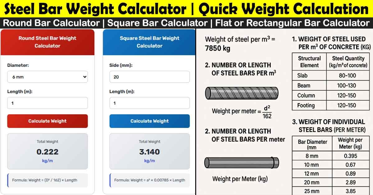
Steel Bar Weight Calculator:
A steel bar weight calculator is an online tool used to estimate the weight of a steel bar based on its dimensions, such as length and diameter.
The calculator works by using the specific gravity of steel, which is typically 7.85 grams per cubic centimeter, to calculate the weight of the steel bar. Steel Bar Weight Calculator
Related Posts:
- Bar Bending Schedule – A Step-By-Step Guide For Rebars BBS
- 90+ Thumb Rules For Civil Engineering & Quantity Surveyors | Formulas
- Method Statement For Cast In Place Concrete Works
FAQs:
What is a Bar Bending Schedule (BBS) formula?
If you’re in the field of civil engineering or construction, you’ve likely come across the term “Bar Bending Schedule” or BBS formula.
Essentially, this is a mathematical equation that serves as a valuable tool for both engineers and contractors alike. It helps to calculate the precise number, length, and weight of steel bars needed for construction projects.
Why is a Bar Bending Schedule important?
A Bar Bending Schedule is important because it helps to ensure the safety, strength, and durability of the structure by providing a clear guideline on the number, length, and placement and quantity of steel bars required.
Why is a Bar Bending Schedule formulas necessary for construction projects?
A Bar Bending Schedule formula is necessary for construction projects because it helps to determine the amount and quantity of steel reinforcement required for a structure, which is crucial to ensure the safety and durability of the building.
How do you calculate the weight of a steel bar using a Bar Bending Schedule formulas?
The weight of a steel bar can be calculated using the formula:
Weight = (d^2/162) x L,
where d is the diameter of the steel bar in millimeters and L is the length of the steel bar in meters.
How do you calculate the number of steel bars required using a Bar Bending Schedule formulas?
The number of steel bars required can be calculated using the formula:
Number of Bars = (Span / Spacing) + 1.
What is the bending length of a steel bar in a Bar Bending formula?
The bending length of a steel bar is the length of the steel bar required to form a specific shape or bend in the structure. It is calculated using the formula:
Bending length = (Total arc length of bend x 180° x D) / (π x angle of bend).
Mostly we use,
1d = 45 degree bend,
2d = 90 degree bend,
3d = 135 degree bend and
4d = 180 degree bend
where d is the diameter of bar
What are the common tools and software used for preparing a Bar Bending Schedule?
The common tools and software used for preparing a Bar Bending Schedule include AutoCAD, Excel, and other computer-aided design (CAD) software.


Could you forward for the construction / installation phase of the concrete scope of work: how would you factor the installation man-hours/crew size ratio for the development of a schedule. The schedule would outlining the following steps: rebar placement, formwork placement, concrete pour , concrete curing time, concrete stripping. The duration would be calculated using what means of method.
Thanks for comment, For more related posts please visit Civil, Arch, Electrical and Mechanical Tab in File menu
Could you forward BBS details
Exalent information …for civil engineers sir
important information
thanks
Thanks u
Helpfull Information.
Thank you sir…
best for the civil engineers.
The best for civil engineering departments
Thanks for comments please get in touch for more knowledge
It was very nice to visit your website and I got very good information
Thanks for comments please get in touch for more knowledge
If you don’t mind, will you send this PDF, sir? It is more helpful to me sir
thanks for reply
Please Check Cutting Length of Diamond Stirrup Formula , L = (Hx4)+ a + 2x10d – 3x2d – 2x3d
Why a ??
now check