Last updated on: April 22, 2022
Method Statement for Earthing and Lightning Protection System | Grounding System Installation
In this article today we will talk about the Method Statement for Earthing and Lightning Protection | Lightning Protection Methods | Method Statement for Grounding System Installation | Installation of Earthing and Lightning Protection System | Earthing Pit Installation | Soil Resistance Test | Soil Resistivity Test | Ground Resistance Tester | Earthing and Lightning Protection System
Method Statement for Earthing System Installation:
1. Purpose:
The purpose of generating this method statement is to define the procedure for Installation of Earthing System (Grounding System) through the guidelines contained herein to ensure that the job execution complies with the requirements where applicable in the project. Lightning Protection Methods
2. Scope:
This method statement covers all processes related to Installation of the mentioned system as per project specification, Manufacturer recommendations, approved drawings, Civil defense approval and regulation. Lightning Protection Methods
3. Reference:
- Design Drawing
- Shop drawings
- Project Specifications
- Material Transmittal
- Project Quality Plan
- Project HSE plan
- Civil Defense approval. Lightning Protection Methods
- Programme Minimum H&S Construction Standard
4. Material and Equipments:
The Following tools shall be arranged before starting the job. All Materials are as per specifications and approved material submittal. Lightning Protection Methods
- Copper clad Earth Rods Shall be UL listed.
- Earth Rod to Tape Clamps
- Earth Rod to Cable Clamps
- U-Bolt Clamps
- Re-bar Clamps
- PVC pipe
- Concrete Earth Inspection Housing
- Cable lugs
- Earth Bars Lightning Protection Methods
- Flexible Copper Braid Bonds
- Welding Machine & Welding mold (Expiry of exothermic welding mold is function of
frequency of application and shall be as per the manufacturer recommendation) - Welding rod
- Safety requirements tools such as safety shoes, safety helmet, safety glasses, fluorescent vest, and safety gloves to ensure maximum ability of safe work and dust mask when require. Lightning Protection Methods
4.1 Material Handling and Storage:
On receipt of the Earthing materials at site necessary precautions shall be taken for unloading, shifting & storage as follows:
- Material shall be stored in a covered / dry space at all the time to avoid corrosion.
- All materials received at site shall be inspected and ensured that the materials are as
per approved material submittal. - Any discrepancies, damage etc., found will be notified and reported for further action.
- Material found not suitable for site use will be removed from site immediately.
- Storage of exothermic welding materials should be in a clean, dry, “NO SMOKING” area and should be restricted to access by authorized personnel only.
- Storage condition shall be such that exothermic welding materials are not subject to rough handling or physical damage. Storage shall be in cool place and in condition no humidity and moisture. Earthing Pit Installation
- All boxes or container of material should be stored in accordance with container (carton) or label marking “This Side Up”
- These materials must be stored under shelter to protect the boxes from the elements and raised to protect them from dampness or wet surface. Earthing Pit Installation
5. Health and Safety:
- Ensure only trained Authorized & licensed persons only shall operate the power tools and do the Installation and Testing job.
- Necessary PPE to be used while working in energized to be worn while working in energized circuits. Ensure adequate lighting is provided in the working area at night time and if inside the building area to be well illuminated.
- Ensure service area/work area openings are provided with barricade, tape, safety nets and warning signage to be provided.
- Calibrated Instruments only to be used.
- Power supply used to take temporary power supply shall not have any joints.
- Ensure LOTO procedure to be followed and implement comprehensive logout & tag out during execution of work. Earthing Pit Installation
6. Installation of Earthing System:
6.1 Installation of Exothermic Welding System:
The mould crucible with suitable size shall be used for exothermic welding:
- The following procedures shall be followed before conduct the exothermic welding:
- Ensure that the mould is always clean and free of moisture
- Ensure that the tap hole is always in well-defined condition
- Ensure that the correctness of connection selector
- Ensure that the correctness of welding powder Earthing Pit Installation
- Procedure to conduct the exothermic connections
- Fix the connection selector to the handle clamp as per the require sizes of
conductor to be welded. - Place the conductor in the mould, ensure that connection selector is used in
accordance to the conductor to be welded. - Close the handle clamp and lock in the lock position, drop the metal retaining disc
into the bottom of the mould crucible. Ensure that the metal retaining disc is correctly, completely seated and cover up the tap hole. - Deposit the welding power into the crucible and spread
mould edge as a role of starting power - Close the mould lips, and ignite with the flint gun
- Open the mould after a few seconds where the reaction is completed or the metal
has been solidified Earthing Pit Installation - Do not touch the welding surface after the reaction
- Clean up the mould for the next joint
- Fix the connection selector to the handle clamp as per the require sizes of
6.2 Earth Electrode:
Earth electrode is to consist of one or more earth rods, interconnected by buried earthing
tape or cable Earthing Pit Installation
6.3 Earthing Cable Installation:
- The earthing conductor, bare copper cable shall be installed as per approved shop
drawing. - Ensure that the copper cable is straight (not wavy) so that it fits nicely into the
exothermic mould prior to the exothermic welding. - Ensure that the copper cable is free of dirt / oil and dry keeping.
- Size and type of supplementary & equipotential conductors shall be as per the approved
shop drawings and stipulated in the contract specification. - Earthing conductors for equipment chassis and neutral and all other panels and mechanical equipment and metal work, shall be as per approved shop drawing and
contract specification. Ground Resistance Tester - Test links shall be installed as shown on the approved shop drawings.
6.4 Earth Rod Installation:
- The copper rod is to be driven into the ground by means hammer drill / sledge
hammer. - Make sure the rods are coupled with coupling and driving studs before hammering as it will protect the thread or the head of the rods from damaged.
- While sitting earth rods, ensure that resistance areas associated with individuals rods do not overlap. Spacing of parallel installed earth rods of length L Shall be L to 2L.
- Earth rods are to be located at a distance greater than 1 m horizontally from foundations of buildings.
- Conductive filler such as Marcionite or Bentonite or equal filler that will not corrode is
to be provided around the Rod. Ground Resistance Tester - After the desired depth has achieved, the earthing conductor will be joint to the earth
bar I rod clamp of the earth pit and fastened it securely. - Resistivity check should be taken and if the resistivity is not achieved to required
value (not to exceed 5 Ohms) then it is advisable to drive it deeper. - The number of rods driven into the ground will be dependable to the soil resistivity on
that particular area and as per approved shop drawing. - Additional rods and network shall be driven if needed to active 5 ohm resistivity.
6.5 Earth Pit:
Precast, square or circular section concrete hand hole (minimum 450mm internal diameter), with concrete cover and extending to 150mm below top of earth rod. Cover earth rod connector with suitable protective compound, which can be easily removed for inspection. Connector is not to be covered with backfill material and is to remain clean.
- Install the inspection pit and ensure that it is flush with the external ground / road level.
- Minimum length of Rod is 2.4m, extendable as necessary to obtain required earth
resistance, Ground Resistance Tester - Ensure that the earth pit is free from dirt and rubbish.

6.6 Type of Connection:
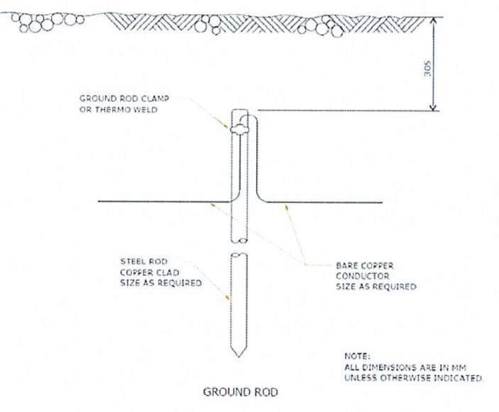
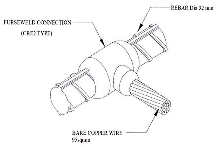
- Connect earth rod to bare copper wire
- Connect rebar to bare copper wire
- Connect copper bar to bar copper wire Ground Resistance Tester
- Connect cable trays/ladders and pipes to grounding system (Detail of electric continuity for cable tray shall be provided in method statement for trays/ladders installation.).
6.7 Earthing Conductors:
- Buried earthing conductors are to be laid at a minimum 750mm depth below finished grade level. Ground Resistance Tester
- Earthing conductors are to follow shortest path between earth rods and main earthing
terminals or bars, and are to run in PVC conduit (duct) fastened to building structure by
approved supports and extending 0.2m above level, and to be protected against mechanical damage and corrosion - Protective conductors which are not part of a cable are to be fixed on same support or
drawn into same conduit as circuit conductors. Ground Resistance Tester
7. Execution Work for Earthing of Lightening Protection:
- Drive the earth rods into the earth by hammer.
- Excavate a trench with standard dimensions or as mentioned in specifications to link earth rods together by soft drawn bare copper wire.
- Link earth rods to Grounding network.
- Testing and record earthing resistant value.
- Joints shall be protected against rust by cold galvanized paint.
- Contact surfaces shall be flush prior to joining. Soil Resistivity Test
- Bolt connections of copper wire with hot dip galvanized steel bar and copper wire with
copper bar should reach mechanical effect and electrical effect. - During the driving of the rods into the earth, it is better to measure value of the resistance to earth in order to quantity of necessary grounding rod.
8. Standard Procedures:
- All equipment’s connected to power supply must be grounded.
- All metal parts, structural steel, cable trays, piping, reinforced concrete must be grounded. Soil Resistivity Test
- All joints shall be according to shop drawing.
9. Safety Control:
- To secure an exit entrance whenever it has contingencies.
- Keep water out where is necessary.
- To keep workplace and amenities is always clean.
- Barricade and sign post are available around the site work.
- To pay attention to equipment’s/tools as below:
- Welding machine insulation Soil Resistivity Test
- Drill machine: insulation and earthing terminal
- Cylinders: Pressure Gauge Set shall be inspected by authorities
- Cutting machine: insulation and earthing terminal
10. Inspection and Testing Procedures:
10.1 Inspection:
- The Grounding System shall be given a visual inspection by the Engineer during the installation
- The Contractor should not allow any backfilling of trenches or pits where these systems are installed before inspection by the Engineer and the appropriate documents are signed. Soil Resistivity Test
- Material delivered shall be inspected under the Engineer’s supervisor about type and size of earth conductors shall be as shown on the approved shop drawings and stipulated in
specification. - Shop-drawing approved.
- Material approved.
- Test method of visual
- Check quality of grounding conductor and grounding electrode delivered on site.
- Check installation (connection, routing, and quantity) according to approved shop drawings.
- Check dimension, level and finishing of foundation of air terminal.
- Check installation according to approved shop drawings and manufacturer’s recommendation.
- Functional Test: As per design and manufacturer’s recommendation.
- Grounding Resistance Value shall be measured.
- Earth connecting bar shall be 50 x 6 mm installed on porcelain insulators.
10.2 Field Test:
- Grounding rods shall be tested for ground resistance value before any wire is connected.
- Ground resistance shall also be measured for each piece of equipment to the ground
electrode. Testing shall be with a portable ground testing megger for each ground or
group of grounds. The instrument shall be equipped with ammeter reading directly in
Ohms or fractions thereof to indicate the ground value of the electrode under test. - All test equipment including test meter shall be provided and one copy of the ground
megger manufacturer’s directions, including the method shall be provided. - Updating of calibration certificate of test instruments.
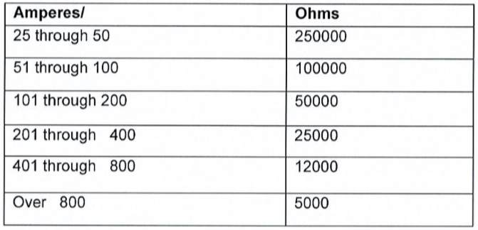
- The minimum resistance based on the allowable capacity of the conductor shall be as
indicated in the following table: Soil Resistance Test
Resistance Test Table:
- The earth resistance shall be measured either soil resistivity testing or earth resistance
testing method. Soil Resistance Test
10.3 Soil Resistivity Testing:
A number of measuring techniques are described in detail in IEEE Std 81-1983. The Wenner four-pin method is the most commonly used technique. (Ref. IEEE Std 80-2000 Page 53).
Four probes are driven into the earth along a straight line, at equal distance a apart, driven to a depth b. the voltage between the two inner (potential) electrode is then measured and
divided by the current between the two outer (current) electrodes to give a value of resistance R Method Statement for Grounding System Installation
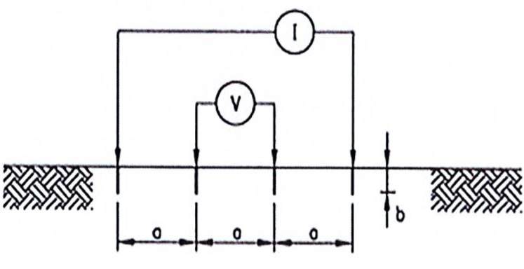
If b is small compared to a, then the equation for Soil resistivity is:
f = 2 x 3.14 x a x R
f = soil resistivity (ohm meters)
a = electrode spacing (meters)
R = measured resistance (ohms)
10.4 Test Procedure:
- Confirm the proposed test locations.
- Insert four electrodes into the ground in a straight line a= 2 meters spacing.
- Connect instrument to the electrodes as shown above.
- Perform test and record measured resistance in Soil Resistivity Test Form.
- Shift electrodes to next spacing a= 4 meters and repeat test.
- Repeat tests a= 6 meters, 8 meters and 10 meters electrode spacing.
- Recorded measurements will be analyzed and presented in Soil Resistivity Test Report.
11. Statute of Completion:
After finishing the installation works of Grounding System, inspection shall be carried out and approved by relative parties such as: Consultant, Parson and civil defense.
12. Quality Control and Assurance:
- Material used will be as approved by the Engineer. The sizes and routes routing will be
as per the approved shop drawing. - Earthing materials shall be stored in a place free of water and properly covered to avoid
any damages due to weather affect. - Combined resistance of earth electrodes is to be measured during dry season and
checked against specified resistance. - Engineer to be notified promptly if the resistance to ground exceeds specified values.
- Electrical continuity of all earthing and protective conductors including main and
supplementary equipotential bonding conductors is to be checked. - Earth fault loop impedance of all circuits is to be measured and checked against
calculated impedance figures. Soil Resistance Test
13. Health & Safety Risk and Control:
The safety procedure generally has to be applied for all Engineers, Supervisors, Workers as
following bellow:
- Make sure that all personal protection equipment (PPE) be provided on site before starting work such as helmet, safety boot, safety glasses, glove, mask etc.
- Make sure that PPE must be wear in the correctly way when working.
- Tools and equipment’s shall be inspected by authorized person before carried out the work.
- Barricades and sign posts for warning shall be provided on site.
- Fire extinguishers shall be provided on site wherever exothermic welding works and always ready to use.
13.1 Working with Welding Machine and Exothermic Welding:
- Ensure worker wear safety glasses, gloves, helmet etc.
- Fire extinguisher shall be always ready at work place.
- Welding machine must be checked carefully before using.
- Welder must be qualified and skill.
OTHER POSTS:
-
Method Statement for Electrical Wires and Power Cables Installation
-
Method Statement for Installation of Electrical Conduit and Boxes
-
Method Statement for Interior and Exterior Lighting System Installation
-
Method Statement for Installation of Cable Tray or Trunking
Conclusion:
Full article on Method Statement for Earthing and Lightning Protection | Lightning Protection Methods | Method Statement for Grounding System Installation | Installation of Earthing and Lightning Protection System | Earthing Pit Installation | Soil Resistance Test | Soil Resistivity Test | Ground Resistance Tester | Earthing and Lightning Protection System. Thank you for the full reading of this article in “QA QC in Construction” platform in English. If you find this post helpful, then help others by sharing it on social media. Please share this article on social media for future uses.

