Last updated on: April 22, 2022
Method Statement for Electrical Wires and Power Cables Installation
In this article today we will talk about the Method Statement for Electrical Wires and Power Cables Installation | Electrical Cable Installation | Electrical Cable Pulling | Electrical Cable Termination | Electrical Wiring Installation | Wires and Power Cables Installation | Electrical Wiring System | Method of Statement for Installation of Wires and Cables | Low Voltage Cable Installation
Method Statement for Electrical Wires and Power Cables Installation:
1. Purpose:
The purpose of generating this method statement is to define the procedure for the Installation of Electrical Wires and power cables through the guidelines contained herein to ensure that the job execution complies with the requirement where applicable in the project. Electrical Cable Installation
2. Scope:
This method statement covers all processes related to the installation of the mentioned system as per project specification, manufacturer recommendation, approved drawings, Civil defense approval, and regulation. Electrical Cable Installation
3. Reference:
- Panel schedule
- Shop drawings
- single line diagram
- Specification of Project
- Material submittal
- Project Quality plan
- Project HSE Plan
- Civil Defense Approval Electrical Cable Pulling
- Programme Minimum H&S Construction Standard
4. Equipments:
The Following tools shall be arranged before starting the job Tool Box.
- Mini Hacksaw Frame with Blades
- Choke Lime Powder with sufficient length of Thread
- Measuring Tape
- End Cutter Low Voltage Cable Installation
- Ladder / Scaffolding
- Manual Auger Bit
- Hammer Electrical Cable Pulling
- Drill M/C portable hand tools
- Portable drill M/C grinding M/C
- Spirit level & water level
- Step ladder
- Hacksaw/Jigsaw M/C
- Centre punch
- Wooden hammer
- Electrical drill (only for surface installation works)
- Diagonal-cutter pliers
- Shank screwdriver Electrical Cable Pulling
Safety requirements tools such as safety shoes, safety helmet, safety glasses, fluorescent vest, and safety gloves to ensure the maximum ability of safe work and a dust mask when required. Electrical Cable Pulling

5. Risk & Safety:
- Ensure only trained Authorized & licensed persons only shall operate the power tools and do the Installation and Testing job. Low Voltage Cable Installation
- All hand tools and power tools shall be good in quality and working condition.
- Personal Protective Equipment ( PPE) required varying types of works.
- Always check and inspect if the scaffolding, ladder used for fixing supports, boxes and
conduits are on safe condition and position before starting the work activities. - Be sure that all access for installation of fixing supports, boxes and conduits have no
obstruction at all times that may cause accident. - Safety signboard, and barricades shall be erected in the working areas if required.
- Necessary PPE to be worn while working in energized to be worn while working in energized circuits. Ensure adequate lighting is provided in the working area at night time and if inside the building area to be well illuminated.
- Ensure service area/work area openings are provided with barricade, tape, safety nets and warning signage to be provided.
- Calibrated Instruments only to be used. Electrical Cable Pulling
- Power supply used to take temporary power supply shall not have any joints.
- Ensure LOTO procedure to be followed and implement comprehensive logout & tag out during execution of work.
- “LOTO” of electrical supplies must only be carried out by a competent person.
- Where cables are laid on the ground they should have additional protection by means of a reinforced sleeve, concrete haunching or timber covers, all protective covering should be clearly marked so as not to constitute a tripping hazard.
- All overhead cables should be routed as far away as possible form access roads, existing
buildings and areas on which buildings are to be erected - Illumination level shall be check periodically and recorded. Ensuring that lighting provided is adequate (minimum of 100 Lux) at workplace area and that personnel are not working in shadow. Electrical Cable Pulling
- Supervisors shall ensure that the light Intensity will not cause vision disturbance. All points of exit, pathways and muster points shall be clearly illuminated. Ladder accesses and egress shall be clearly illuminated. Electrical Cable Termination
- Ensure good housekeeping at all times, keep work area clear from obstruction.
- The working environment may be improved by ensuring adequate space for handling
operations and ensuring that walking surfaces are free of obstructions.
6. Procedure or Methodology:
6.1 Work Sequence:
- Check all material delivered to site is inspected properly by QA/QC Inspector and check if it is stored properly as per manufacturer’s recommendations.
- MIR shall be raised for the inspection of materials received at site to the Consultant Engineer. Electrical Cable Pulling
- Work shall be carried out by the site staff under strict supervision and guidance of the
concerned Supervisors / Foremen / Engineers. - The QA/QC Inspector shall check all the installations as per the Installation Check list.
- WIR shall be prepared by QA/QC Inspector and will be submitted to Consultant for their
inspection and approval. Electrical Cable Termination - QA/QC Inspector shall coordinate with other contractors and arrange inspection for installation to the Consultant Engineer.
- QA/QC Inspector is responsible for all installation activities for getting the work inspected and approved by Consultant Engineer.
6.2 Handling and Storage:
- On receipts of the material at site, necessary precautions shall be taken for unloading, shifting and Storage, as follows: Electrical Cable Termination
- On the floor, the units will be stored in a clean, dry place and adequate covering by tarpaulin sheets will be done to protect the wire/ cable from disposition of construction dust till it is finally shifted to its location.
- All Material received will be checked to ensure that they are complying with the approved material submittals in terms of their make, model, type, capacity, etc.,
- Any discrepancy or damages etc., it will be notified and reported immediately for further action. It should be noted on the carrier’s freight bill. Damage claims should be filed with the carrier immediately. Low Voltage Cable Installation
- Material found not suitable for site use will be removed immediately from site and the same will be replaced by correct equipment.
- Site Engineers have to ensure that all material used at site are of free from any damages or deformities of any kind. Units found not suitable for site use will be removed immediately and the same will be replaced by correct item.
- End of cables shall be sealed to prevent ingress of moisture.
- Each cable drum shall be provided with appropriate weatherproof metallic label indicating project name, order no., type, size and length of the cable delivered
- The reels for small building wires shall be provided with appropriate tags indicating at least the type, size and length of wire delivered. Electrical Cable Termination
6.3 Pre Installation of Cables:
- Installation shall be in accordance with the SASO, IEEE, IEC, NEC, BS and IPCEA and local codes, as shown on the drawings, and as recommended by the major equipment
manufacturer. Electrical Cable Termination - Ensure that all relevant documents have been approved by DAR Engineer prior to commencing installation, and that the latest revisions of shop drawings, specifications
including approved procedures are distributed to concerned personnel who will carry out the work. Low Voltage Cable Installation - Ensure that all personnel are qualified to perform the work and are fully familiar with all the tools and equipment’s to be utilized.
- Check Cables and its accessories for damage before transporting to the work area. All
materials of unapproved/damage condition or low quality shall be immediately segregated from the job site to a confined area. - Check and confirm actual proposed routing layouts against approved shop drawings.
- Ensure that the area is safe. For above ground installation, ensure adequate scaffold Ladders and access ways are available at the work location.
- Ensure that the transport of the materials should be thoroughly planned.
- Ensure that the area of installation is ready.
- Ensure that Cables and Accessories that needs to complete the work are available at
designated areas scheduled for installation, and they meet the correct size and the routing layouts are in accordance with approved shop drawings. - Daily housekeeping shall be conducted after work specially to remove left-over materials
from the work area. Electrical Cable Termination - Coordination shall be done with other disciplines prior starting any installation
6.4 LV Wires and Cables Installation:
- LV Power cables, building wires and control cables are to be installed in accordance with
manufacturer’s instructions and as per approved shop drawings. - Ensure Conduits / raceway installations are completed between outlet, junction boxes,
electrical cabinets or splicing points prior to the installation of conductors. - Verify that bushings are installed in each junction box, pull box and electrical cabinet prior to cable pulling / laying.
- Installation of Conductors with Other System- Raceways containing electric conductors shall not contain any pipe, tube, or equal for steam, water, air, gas, drainage, or any service other than electrical. Electrical Cable Termination
- Ensure the burs and sharp edges in conduit and raceway are removed and it is dry and
clean before pulling wires in conduit check. - Check the cable schedule and the single line diagram to ensure that cable type and size are correct prior to cable pulling/laying.
- Perform continuity test on power cables, wires and control cables on cable reel prior to
cable pulling. Electrical Cable Termination - Clean the area after completing cable pulling.
- Color coding should be maintained throughout the installation. Phase-conductors should
be engraved with alphanumeric mark (LI, L2, L3) or color coded heated shrinkable
sleeves. Electrical Wiring Installation - Control and signal cables, enclosed in conduit and raceways with power cables, are to be
insulated for same voltage grade. - Control cables should be fixed to racks and installed directly on cable trays or pulled in
conduits and trunking indoors and in underground ducts or in conduits outdoors. - Ensure Lubricants are used for pulling wire or cable to avoid damage on conductor
insulation. - Ensure to leave extra cable length for cables terminating in branch circuit outlet and pull
box. Low Voltage Cable Installation - Insulating covers are to be applied to prevent exposure of bare cable connections.
- Temporary protection cover shall be made on the ends of cables to avoid moisture
absorption to the cable strands and temporary identification label shall be made at each
end; the identification shall be as on the cable pull-sheet. Final label or identification will
have to be installed after termination is completed. - Ensure each main and feeder cables in pull-boxes, wire ways and circuits of panel boards or distribution boards will be fitted with an identification tag. This tag will indicate the identity of cable or circuit number and conductor size in accordance with the schedules.
- Each cable shall be dressed to provide a straight installation along its entire length.
- Dress the cables, removing all temporary tie wraps and securing with permanent tie wraps.
- Mark-up / As-built drawings for any changes made.
- Cross check cleanness and sharp edges of cable tray before cable pulling’s.
- Proper type, size, colour and number of wires and cable are being installed.
- Ensure cables are to be run through duct-banks, shafts, clamped to steel racks or cable trays. Electrical Wiring Installation
- The conductor of all single core wires shall be of high conductivity, plain circular standard, and annealed copper conductors.
- The insulation of single core wires shall be heat resistive PVC type 5 to BS 6746, rated at
85°C for continuous operation. Manufacturer shall guarantee that insulation will not emit
any toxic fumes in the event of a fire. - The building wires shall comply with BS 6004 Table 5, rated 600/1000V grade for power Wiring and 450/750V grade for lighting applications.
- The pulling tension of the wire shall not exceed the maximum tension recommended by the cable manufacturer. Low Voltage Cable Installation
- No conductor smaller than 2.5mm2 shall be used for lighting installation and 4. Osq.mm for small/equipment power installation.
- Single core PVC insulated wires in trunking or conduits for internal wiring.
- Not more than 2 final sub-circuits shall be run in any conduit.
- Provide color coded ferrules and circuit number tags for termination of wires.
- Wires insulation resistance and continuity tests shall be carried out with 500V megger updating calibration certificate is required.
- Max. no of sub circuit run in one conduit, is two.
- Conduit manufacture recommended wire pulling compound shall be utilized and not the
soap agent. - Wire color code shall be as show on the approved shop drawings and as per IEE Regs.
Requirements. Electrical Wiring Installation - Earth cable shall run in parallel and tied to power cables at proper intervals.
- Keep 300mm between wire / power cables and control cables.
- Cable that are buried must be installed in a trench with a minimum depth of 0.75 meter and must have a cable marking tape laid over it 20cm. from the top of the trench. The line of burial must be clearly marked with signs.
- Where cables are valid on the ground they should have additional protection by means of a reinforced sleeve, concrete hunching or timber covers, all protective covering should be clearly marked so as not to constitute a tripping hazard.
- All overhead cables should be routed as far away as possible from access roads,
existing buildings and areas on which buildings are to be erected. - Normal and emergency sub circuits shall run in different conduits or in same trunking fitted with separation. Electrical Wiring Installation
6.5 Feeder and Sub Feeder Installation:
- Ensure cables are to be run through duct-banks, shafts, clam ped to steel racks or cable trays. Electrical Wiring Installation
- Cables running thru ventilation shafts is not allowed
- Ensure that when two or more cables run in parallel, they have to be fixed on galvanized
steel perforated trays or on other approved special cable supporting and protecting arrangement. Low Voltage Cable Installation - Steel clamp / cleat shall not be used for single core cables.
- Ensure Cables are to be supplied in sufficient lengths for straight – through un-jointed
termination to termination pull. - Ensure that joints or splices will not be accepted on main and sub-feeders.
- Direct buried cables crossing under roads, pipe banks or other services are to be laid in
heavy duty PVC duct banks. - Ensure no cables are to install directly buried in concrete, in masonry or in finished floor.
- Insulating covers are to be applied to prevent exposure to excessive heat or to corrosive
agents. Low Voltage Cable Installation - Joints shall not be allowed in any cable, unless a prior written approval of an engineer is
obtained. - The pulling tension of the cable shall not exceed the maximum tension recommended by the cable manufacturer.
- Proper type, size, colour and number of the cables are being installed.
- Place cable drums at elevated & rolling position, so as to pull the cable without twists.
- Pull cables using cable Hooks or ropes.
- Pull the cable smoothly with force recommended by manufacturer.
- Make sure that the cable will run over the cable roller till the end of the cable tray.
- If Cable Hooks will be used fix one end of cable to the hook and tie other end with a rope. Electrical Wiring Installation
- Cable fill is as per required standards.
- LV distribution cables single core or multi-core and un-armored or armored.
- All low voltage distribution cables shall be copper conductors, 600/1000V grade, cross-Linked polyethylene (XLPE) insulated and PVC or polyethylene sheathed cable.
- Core identification at termination shall be done by colored or numbered plastic stretch or
shrink ferrules. Electrical Wiring System - Multi-core XLPE/PVC insulated unarmored cables in cable trays, ladders or
Conduits for internal wiring. - Multi-core XLPE/SWA/PVC insulated armored cables in conduits, cable trays,
Ladders duct banks or direct buried for external wiring - Armoring for single core cables shall be aluminum wire armoring (AWS)
- Provide cable tags at both ends and at intervals not exceeding 25 m.
- Power cables shall be installed above water lines
- Cable radius of bend shall be considered as per the manufacturer recommendation
- Type of LV cables (LSZH), fire resistant…etc.) Shall be as per approved shop drawings,
specification and feeder data schedule. Electrical Wiring System
6.6 LV Cables Connections, Jointing and Termination:
- Prior approval for through joint for LV cable is require.
- Ensure Through joints and terminations are to be carried out in accordance with cables
manufacturer’s recommendation. Electrical Wiring System - Check Joints and terminations are to be made with correct specified materials, boxes, tapes, compounds or mixtures, stress cones, glands and bonds as applicable.
- Sample site constructed cable terminations and through joints are to be submitted prior to commencing work on site in the presence of Engineer and are to be tested and inspected in accordance with manufacturer’s recommendations.
- Ensure proper tools are used for jointing and terminating cables to prevent damage.
- Conductors should be cleaned. Electrical Wiring System
- Ensure Electrical connectors and terminals are tightened in accordance with manufacturers published torque -tightening values or with international standards.
- Once the cable testing is completed the cable lugs will be connected directly through the
terminal box along with bolts and nuts (or equivalent) and fully tightening and ensure the mechanical tension strength of the connection and with proper cable identification number tagging. Electrical Wiring System - Termination kits I color boots and crimped lugs shall be provided for termination of cables. Proper IP rating cable gland and shroud shall be provided. A slack of cable shall be maintained of future reconnection. Bolting tightness of cables into circuit breakers shall be checked by calibrated torque wrench. Electrical Wiring System
6.7 Installation Resistance Test:
- Check installed wires and cables with mega ohm meter to determine insulation resistance levels to ensure the requirements are fulfilled.
- Establish that cable route drawings /single line drawings are available identifying test
limits. Electrical Wiring System - Ensure both ends of the cable are disconnected and isolated.
- Ensure test equipment (megger tester) is available with a valid calibrated certification.
- All test equipment used for the testing of the cable shall be certified and the certification
period shall be Certification period shall not exceed 1 years. Calibration Sticker showing all information including signature, attach to the test equipment. - Ensure Cable tests are to be carried out in accordance with the requirements of the
regulations and standards. Electrical Wiring System - Test each conductor for phasing, continuity and insulation resistance (meggar).
- After completion of the installation of L.V. cables and wires, carry out continuity, insulation Resistance test for 1 minute at 500 V or 1000 V, according to the rated voltage of the Cables/wires under test. The test voltage shall be applied between the conductors and Between each conductor and earth/neutral and shall comply with the requirements of IEE Wiring Regulations. Wires and Power Cables Installation
- Insulation resistance for LV power and lighting installations is to be measured out in
accordance with BS7671 (The IEE wiring Regulations) - Upon test completion, cables shall be left with all cores and screens grounded for about an hour to allow residual charge to dissipate.
- Cable ends should be protected from moisture using electrical tape.
- After completion of testing the cable ends shall be sealed to prevent the ingress of moisture. Wires and Power Cables Installation
- Multi-core power cables shall not be run inside cable trunking.
- The permanent radius of cables bend at any location after installation shall not be smaller than the cable Manufacturer’s recommendations.
- Cables are supported on cable tray; they shall be fixed to the cable tray using suitable
approved straps or clips. Ties shall be spaced at not greater than 600 mm - Intervals along each cable, and within 100 mm of each bend or set.
- Care shall be taken to ensure that electrolytic action does not take place between dis-similar metals used for cable trays, ladders, supports, clamps, etc.
OTHER POSTS:
-
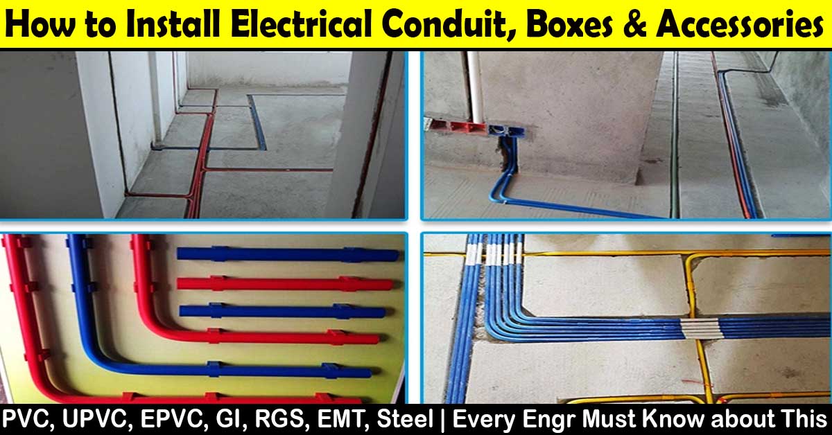
Method Statement for Installation of Electrical Conduit and Boxes
-
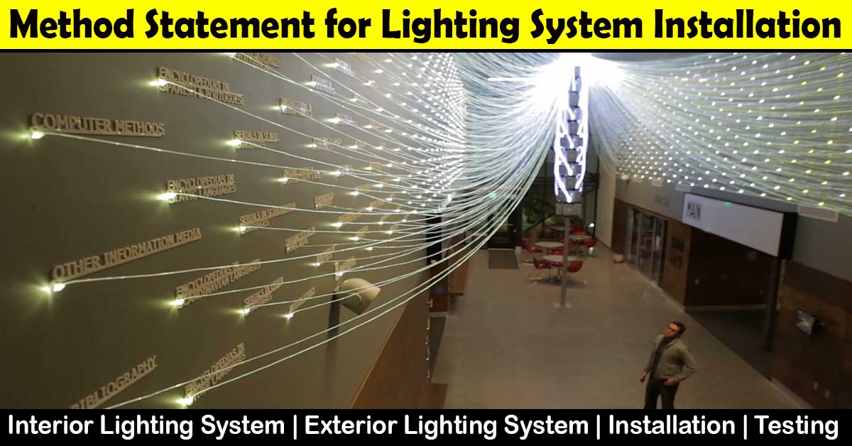
Method Statement for Interior and Exterior Lighting System Installation
-
Method Statement for Installation of Cable Tray or Trunking
-
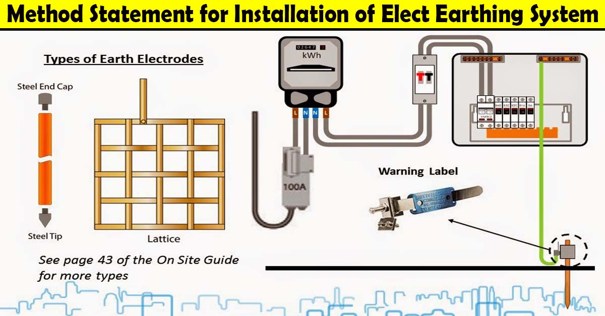
Method Statement for Earthing and Lightening Protection System
Conclusion:
Full article on Method Statement for Electrical Wires and Power Cables Installation | Electrical Cable Installation | Electrical Cable Pulling | Electrical Cable Termination | Electrical Wiring Installation | Wires and Power Cables Installation | Electrical Wiring System | Method of Statement for Installation of Wires and Cables | Low Voltage Cable Installation. Thank you for the full reading of this article in “QA QC in Construction” platform in English. If you find this post helpful, then help others by sharing it on social media. Please share this article on social media for future uses.


how to use, ?