Last updated on: April 23, 2022
Method Statement for Installation of Cable Tray or Trunking with Accessories
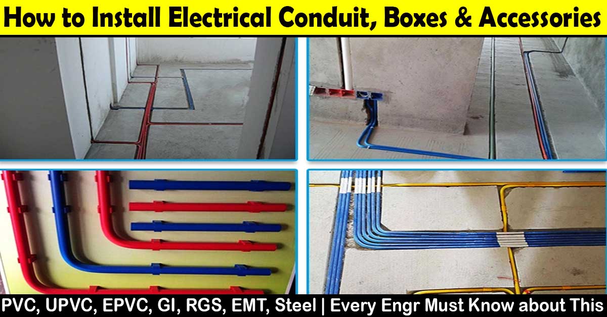
In this article today we will talk about the Installation of Cable Tray or Trunking | Method Statement for Electrical Works | Cable Ladder Installation | Electrical Cable Installation | Floor Trunking for Cables Installation | Cable Support System | Wiring Installation | Cable Tray System Installation | Cable Trays for Electrical Systems
Method Statement for Installation of Cable Tray or Trunking:
1. Purpose:
The purpose of this method statement is to describe the Installation of cable trays and Trunking. Method Statement for Electrical Works
2. Responsibilities:
Responsibilities for ensuring that the steps in this procedure shall be carried out are specified at relevant steps in the procedure:
- Project Manager
- Construction manager
- Site Engineer
- QA/QC Inspector
- HSE officer
- Site Foreman
- SK Method Statement for Electrical Works
2.1 Project Manager:
Project Manager is overall responsible for the project in terms of work execution, safety,
planning & quality. The Project Manager will maintain the planning progress and coordination of works with the main contractor.
The work progress shall be carried out as per planned program and all the equipment’s
required to execute the works shall be available and in good condition as per project planned. Specific attention is paid to all safety measures and quality control in coordination with Safety Engineer and QA/QC Inspector and in line with PQP.
2.3 Construction Manager:
Construction Manager is responsible to supervise and control the work on site. Coordinating with QA/QC Inspector and site Team and foremen for all activities on site. Control and sign all WIR’s before issuing to Consultant approval. Method Statement for Electrical Works
2.4 Site Engineer:
- The method of statement shall be implemented according to the project specifications and approved drawings. Cable Ladder Installation
- Provision of all necessary information and distribution of responsibilities to his Construction team. The work progress shall be monitored in accordance with the planned work program and he will provide reports to his superiors.
- The constant coordination with the Safety Engineer to ensure that the works are carried out in safe working atmosphere.
- The constant coordination with the QA/QC Inspector for any works to be carried out and initiate for the Inspection for the finished works.
- Should acquire any necessary civil works clearances and coordination.
- He will ensure the implementation of any request that might be raised by the Consultant. Efficient daily progress shall be obtained for all the equipment and manpower.
- He will engage in the work and check the same against the daily report received from the Foremen.
- Convey all the revised information to the Foremen and ensure that it’s being carried out properly. Cable Ladder Installation
2.5 QA/QC Inspector:
- The monitoring of executions of works at site should be as per the approved drawings and project specification.
- Ensure WIRs are being raised for activities in timely manner and inspected by the Consultant.
- Check and ensure that all activities / work done I completed prior to offer for consultant inspection.
- He will follow and carried out all the relevant tests as per project specifications.
- Obtain the required clearance prior to Consultant’s inspections. Coordinate with site construction team. Cable Ladder Installation
2.6 HSE Officer:
- The implementation of all safety measures in accordance with the HSE plan and that the whole work force is aware of its proper implementation.
- The implementation of safety measures is adequate to maintain a safe working environment on the work activity.
- Inspection of all the site activities and training personnel in accident prevention and its proper reporting to the Construction Manager and the Project Manager.
- The site is maintained in a clean and tidy manner.
- Ensure only trained persons shall operate the power tools.
- Ensure all concerned personals shall use PPE and all other items as required. Ensure adequate lighting is provided in the working area at night time.
- Ensure high risk elevated areas are provided are barricade, tape, safety nets and provided with ladders.
- Ensure safe access to site work at all times. Floor Trunking for Cables Installation
2.7 Site Foreman:
- The carrying-out of work and the proper distribution of all the available resources in coordination with the Site Engineer on a daily basis.
- Daily reports of the works are achieved and coordinated for the future planning with the Site Engineer. Incorporate all the QA/QC and Safety requirements as requested by the concerned Engineer. Floor Trunking for Cables Installation
- Meeting with any type of unforeseen incident or requirement and reporting the same to the Site Engineer immediately. Floor Trunking for Cables Installation
2.8 Store Keeper:
Responsible for overall Store operations in making sure to store the material delivery to the site and keep it in suitable area that will keep the material in safe from rusty and damage.
One who will acknowledge the receiving of materials at site in coordination with QA/QC and
concerned Engineer. Cable Trays for Electrical Systems
3. Scope of Work:
The method statement is written for the purpose of establishing method and procedures for the installation of cable tray and cable trunking for the building MEP services.
4. Handling and Storage:
- All material shall be stored in proper place.
- Prepare delivery schedule and check site conditions as storage capacity.
- Prior to material delivery to site, conduct site survey and make all necessary access for the safe transportation of material to the designated location.
- Check model and type of material against delivery order.
- Check any damage during transportation. Cable Trays for Electrical Systems
5. Reference:
Reference shall be made to the following documents:
- Project specification for the cable tray and trunking
- Electrical identification section-16030.
- NEMAVE2. Wiring Installation
- Shop drawings Cable Trays for Electrical Systems
6. Installation Sequence:
- Clean the cable tray/ trunking before installation of cables. Install covers after completion of installation. Cable Tray System Installation
- Before starting the installation activities, the approval for shop drawing shall be made & available at site.
- The installation work will start by marking the routing & location of support against cable tray.
- Ensure that work area is ready and safe in co-ordination with safety, mechanical & civil department.
- Surveyor should provide required levels for cable tray and trunking systems from FFL.
- Mark & lineout cable tray routes as per shop drawings and in co-ordination with other utilities. Wiring Installation
- All cable tray shall be of heavy duty perforated type with return flange in non-plenum area a non perforated type with cover in air plenum.
- All cable trays shall be manufactured from hot-dip zinc coated galvanized steel, with a standard heavy duty galvanizing coating of 350g/m2 and Z2 bending grade.
- All fixing brackets, nut and bolts shall be finished by hot dip galvanising accordance of its specification & approved material.
- In outdoor location and area subject to crossing atmosphere, the cable tray/ladders/ trunking shall be painted with chlorinated rubber paint or PVC/Epoxy coating, as approved by the engineer.
- Cable trays and accessories shall be of a thickness of not less than 1.2 mm up to 305mm width and 2.0 mm above 305mm width.
- Tinned copper earth continuity straps shall be provided at every joint of the cable tray and trunking.
- The gap between cable trays support should be as per shop drawing. These bracket shall be secured by using appropriate nuts, bolts, washer & spring nut.
- Where cable tray crossing building expansion joint, the tray shall be installed suitably to provide expansion/ contraction with the building expansion.
- Cable trays/Ladder system support shall be determined in accordance with the manufacture’s structural information to ensure the undue stress or bending shall not occur. Wiring Installation
- All accessories and fittings such as bends, tees, elbow, cross units and angles shall be of the same specification as that of the cable tray finish and shall be standard products from the same manufacture as the cable tray. Site fabrication shall not be permitted.
- Where cable tray carries 13.8 kv cable, a tray lid shall be installed.
- Provide sufficient space around cable tray for access. Cable Support System
- Use fish plate to joint & align cable tray where cable tray passes through fire rated wall, approved fire shop drawing installation method shall be followed.
- On completion of cable tray/ ladder installation including fittings, inspect exposed finish. Remove burrs & construction debris and repair damages finishes including chips, scratches & abrasions.
- Surface/ floor cable trunking shall be used with prior approval of the engineer, wherever possible to replace multiple conduits runs.
- Metal surface/ floor cable trunking shall comply with NEC and shall be manufacturer from galvanized steel sheet.
- Surface/floor cable trunking shall be single or multi-compartment as required. Where multi-compartment is used, vertical dividers shall be provided between the compartments which shall be welded to the trunking prior to galvanizing’s.
- Heavy duty uPVC trunking with clip on lid (all insulated) shall be used if show on the drawings or specified elsewhere. Wiring Installation
7. Acceptance of Equipment’s and Materials:
As per the scope of work, support material and all consumables will be supplied by SAB. All
material supplied by SAB shall be inspected prior to installation to ensure material complied with project standards. Wiring Installation
- Before storing these materials on shelves, certificates and period of validity will be checked, and inventory will be prepared for control. Unqualified material or equipment will be rejected. Wiring Installation
- Material inspection shall be carried from time to time after receiving these materials from warehouse during the installation period according to company specification.
8. Resource:
8.1 Material:
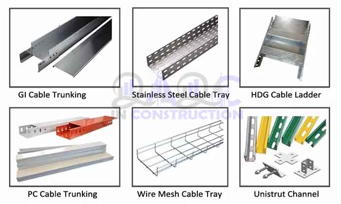
Cable tray perforated / ladder/ trunking & related fittings accessories.
8.2 Equipment Tools:
- Drill M/C portable hand tools
- Portable drill M/C grinding M/C
- Spirit level & water level
- Step ladder
- Hacksaw/Jigsaw M/C
- Measurement tape
- Right angle
- Centre punch
- Wooden hammer
- Electrical drill(only for surface installation works)
- Diagonal- cutter pliers
- Shank screwdriver Cable Support System
- Scaffolding with floor arrangement
- P.P.E personal protective equipment (safety helmet, boots, gloves, & safety vest).
9. Health & Safety Risk and Controls:
The following general control measures against safety, environment and quality shall be required for our scope of work and special control measurement are not applicable for us:
- Proper PPE must be worn at all time.
- Safety induction to labor should be conducted before work will start
- Permit to work at height>2m where applicable
- Lifting operation permit (using crane) where applicable.
- Confined space permit where applicable.
- Inspection of PPE & Scaffolding should be done by H&E Engineer.
- All Workers and engineers should take care of safety while working near open voids and on the edges of room. Safety belt must be worm while working on scaffolding or on any heights. Approved work method statement and risk assessment will be made available to site. All workers doing the work shall be briefed on this method statement and risk assessment.
- Conduct job safety talk before starting the work, and issue daily task assessment.
- Place barricade and warning sign boards in applicable locations. Restrict personnel /
equipment’s entering the work area. - Check adequacy and availability of all tools, before commencement of installation activity.
- The safety officer shall verify that all the necessary and applicable documents, related to the safe site operation are in possession before commencing the job.
- Safety procedures shall be followed at all times.
- Area shall be kept clean at all time. Cable Support System
OTHER POSTS:
-
Method Statement for Electrical Wires and Power Cables Installation
-
Method Statement for Installation of Electrical Conduit and Boxes
-
Method Statement for Interior and Exterior Lighting System Installation
-
Method Statement for Earthing and Lightening Protection System
Conclusion:
Full article on Installation of Cable Tray or Trunking | Method Statement for Electrical Works | Cable Ladder Installation | Electrical Cable Installation | Floor Trunking for Cables Installation | Cable Support System | Wiring Installation | Cable Tray System Installation | Cable Trays for Electrical Systems. Thank you for the full reading of this article in “QA QC in Construction” platform in English. If you find this post helpful, then help others by sharing it on social media. Please share this article on social media for future uses.